(56)

Signals and Systems in the Frequency Domain
Fourier Series
Basic formulas
If x(t) is periodic with period T, then for all t,
 

Description: Description: Description: C:\Users\gwang08\Desktop\MAE315\Website\MAE315\notesNrefs\Fourier\Image1.gif

(1)

and the repetition rate of x(t) is;
 

Description: Description: Description: C:\Users\gwang08\Desktop\MAE315\Website\MAE315\notesNrefs\Fourier\Image2.gif

(2)

Because x(t) is periodic, it can be expressed as a Fourier series, that is as a summation of sinusoids whose frequencies are integral multiples of the repetition rate f0:
 

Description: Description: Description: C:\Users\gwang08\Desktop\MAE315\Website\MAE315\notesNrefs\Fourier\Image3.gif

(3)

The coefficient a0 is obtained by calculating the average value of x(t) over one period [hence, a0 is often called the dc level of x(t)]. Each of the other coefficients is obtained by multiplying both sides of (3)

The coefficient a0 is obtained by calculations the average value of x(t) over one period [hence, a0 is often called the dc level of x(t)]. Each of the other coefficients is obtained by multiplying both sides of (3) by the corresponding sinusoid, and then integrating both sides over one period, Fortunately all the cross products integrate out to zero, and we’re left with the following straightforward formulas:
 

Description: Description: Description: C:\Users\gwang08\Desktop\MAE315\Website\MAE315\notesNrefs\Fourier\Image4.gif

(4)

Description: Description: Description: C:\Users\gwang08\Desktop\MAE315\Website\MAE315\notesNrefs\Fourier\Image5.gif

(5)

Description: Description: Description: C:\Users\gwang08\Desktop\MAE315\Website\MAE315\notesNrefs\Fourier\Image6.gif

(6)

Analysis of the Square Wave

Description: Description: Description: C:\Users\gwang08\Desktop\MAE315\Website\MAE315\notesNrefs\Fourier\Image7.gif

a0 = average value = 0

a1 = 0, and indeed an = 0 for all n, because x(t)cos(2pnf0t) always has the same amount of area above the line as below.

Description: Description: Description: C:\Users\gwang08\Desktop\MAE315\Website\MAE315\notesNrefs\Fourier\Image8.gif

b1Description: Description: Description: C:\Users\gwang08\Desktop\MAE315\Website\MAE315\notesNrefs\Fourier\Image9.gif

Description: Description: Description: C:\Users\gwang08\Desktop\MAE315\Website\MAE315\notesNrefs\Fourier\Image10.gif

b2 = 0, and indeed bn = 0 for all even values of n, because x(t)sin(2pnf0t) always has the same amount of area above the line as below, whenever n is even.

Description: Description: Description: C:\Users\gwang08\Desktop\MAE315\Website\MAE315\notesNrefs\Fourier\Image11.gif

Description: Description: Description: C:\Users\gwang08\Desktop\MAE315\Website\MAE315\notesNrefs\Fourier\Image12.gif

Description: Description: Description: C:\Users\gwang08\Desktop\MAE315\Website\MAE315\notesNrefs\Fourier\Image13.gif
 

Description: Description: Description: C:\Users\gwang08\Desktop\MAE315\Website\MAE315\notesNrefs\Fourier\Image14.gif

 for n odd

Thus,
 

Description: Description: Description: C:\Users\gwang08\Desktop\MAE315\Website\MAE315\notesNrefs\Fourier\Image15.gif

(7)

Reconstruction of a Square Wave

Description: Description: Description: C:\Users\gwang08\Desktop\MAE315\Website\MAE315\notesNrefs\Fourier\Image16.gif

Description: Description: Description: C:\Users\gwang08\Desktop\MAE315\Website\MAE315\notesNrefs\Fourier\Image17.gif

Complex Fourier Series

Define:
 

Description: Description: Description: C:\Users\gwang08\Desktop\MAE315\Website\MAE315\notesNrefs\Fourier\Image18.gif

(8)

Description: Description: Description: C:\Users\gwang08\Desktop\MAE315\Website\MAE315\notesNrefs\Fourier\Image19.gif

 (9)

Description: Description: Description: C:\Users\gwang08\Desktop\MAE315\Website\MAE315\notesNrefs\Fourier\Image20.gif

(10)

Rearranging (8), (9), and (10), we have:
 

Description: Description: Description: C:\Users\gwang08\Desktop\MAE315\Website\MAE315\notesNrefs\Fourier\Image21.gif

(11)

Description: Description: Description: C:\Users\gwang08\Desktop\MAE315\Website\MAE315\notesNrefs\Fourier\Image22.gif

(12)

Description: Description: Description: C:\Users\gwang08\Desktop\MAE315\Website\MAE315\notesNrefs\Fourier\Image23.gif

(13)

 Recall Euler’s relationship:
 

Description: Description: Description: C:\Users\gwang08\Desktop\MAE315\Website\MAE315\notesNrefs\Fourier\Image24.gif

(14)

Description: Description: Description: C:\Users\gwang08\Desktop\MAE315\Website\MAE315\notesNrefs\Fourier\Image25.gif

(15)

By manipulating (14) and (15) we obtain:
 

Description: Description: Description: C:\Users\gwang08\Desktop\MAE315\Website\MAE315\notesNrefs\Fourier\Image26.gif

(16)

Description: Description: Description: C:\Users\gwang08\Desktop\MAE315\Website\MAE315\notesNrefs\Fourier\Image27.gif

(17)


By substituting (2pnf0t) for q in (16) and (17), and substituting that result, along with (11), (12), and (13), all into (3), and rearranging terms, we get the Complex Exponential Form of the Fourier Series
 

Description: Description: Description: C:\Users\gwang08\Desktop\MAE315\Website\MAE315\notesNrefs\Fourier\Image28.gif

(18)

Description: Description: Description: C:\Users\gwang08\Desktop\MAE315\Website\MAE315\notesNrefs\Fourier\Image29.gif

(19)

NOTE:
 

Description: Description: Description: C:\Users\gwang08\Desktop\MAE315\Website\MAE315\notesNrefs\Fourier\Image30.gif

(20)

Application to a Pulse Train

Description: Description: Description: C:\Users\gwang08\Desktop\MAE315\Website\MAE315\notesNrefs\Fourier\Image31.gif

From (19), we obtain
 

Description: Description: Description: C:\Users\gwang08\Desktop\MAE315\Website\MAE315\notesNrefs\Fourier\Image32.gif

(21)


Description: Description: Description: C:\Users\gwang08\Desktop\MAE315\Website\MAE315\notesNrefs\Fourier\Image33.gif

Fourier Transforms

Basic Formulas

Start with complex exponential form of Fourier Series, (18) and (19), and define a quasi-continuous variable
 

Description: Description: Description: C:\Users\gwang08\Desktop\MAE315\Website\MAE315\notesNrefs\Fourier\Image34.gif

(23)

Description: Description: Description: C:\Users\gwang08\Desktop\MAE315\Website\MAE315\notesNrefs\Fourier\Image35.gif

(24)

and define
 

Description: Description: Description: C:\Users\gwang08\Desktop\MAE315\Website\MAE315\notesNrefs\Fourier\Image36.gif

(25)

Substituting (23) and (25) into (19), and substituting (23), (24) and (25) into (18), and letting Description: Description: Description: C:\Users\gwang08\Desktop\MAE315\Website\MAE315\notesNrefs\Fourier\Image37.gif (i.e., a "single period" over all time) yields:

Fourier Transform
 

Description: Description: Description: C:\Users\gwang08\Desktop\MAE315\Website\MAE315\notesNrefs\Fourier\Image38.gif

(26)

Description: Description: Description: C:\Users\gwang08\Desktop\MAE315\Website\MAE315\notesNrefs\Fourier\Image39.gif

(27)

Description: Description: Description: C:\Users\gwang08\Desktop\MAE315\Website\MAE315\notesNrefs\Fourier\Image40.gifand Description: Description: Description: C:\Users\gwang08\Desktop\MAE315\Website\MAE315\notesNrefs\Fourier\Image41.gif are called a Fourier transform pair, denoted by:
 

Description: Description: Description: C:\Users\gwang08\Desktop\MAE315\Website\MAE315\notesNrefs\Fourier\Image42.gif

(28)

Description: Description: Description: C:\Users\gwang08\Desktop\MAE315\Website\MAE315\notesNrefs\Fourier\Image43.gif

(29)

A powerful property of the Fourier transform can be obtained by differentiating (27) with respect to time:
 

Description: Description: Description: C:\Users\gwang08\Desktop\MAE315\Website\MAE315\notesNrefs\Fourier\Image44.gif

(30)

which implies that
 

Description: Description: Description: C:\Users\gwang08\Desktop\MAE315\Website\MAE315\notesNrefs\Fourier\Image45.gif

(31)

Description: Description: Description: C:\Users\gwang08\Desktop\MAE315\Website\MAE315\notesNrefs\Fourier\Image46.gif

(31a)

Example of a Single Pulse

Description: Description: Description: C:\Users\gwang08\Desktop\MAE315\Website\MAE315\notesNrefs\Fourier\Image47.gif

From (26), we have:
 

Description: Description: Description: C:\Users\gwang08\Desktop\MAE315\Website\MAE315\notesNrefs\Fourier\Image48.gif

(32)

Description: Description: Description: C:\Users\gwang08\Desktop\MAE315\Website\MAE315\notesNrefs\Fourier\Image49.gif

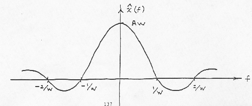
Note: as the pulse becomes narrower in the time domain, its associated frequency spectrum (Fourier transform) spreads out. Similarly, as the pulse becomes wider in the time domain, its associated frequency spectrum becomes compressed around f = 0.

Now let:
 

Description: Description: Description: C:\Users\gwang08\Desktop\MAE315\Website\MAE315\notesNrefs\Fourier\Image50.gif

(34)

Under this condition the area under the pulse will always be unity. In the limit as Description: Description: Description: C:\Users\gwang08\Desktop\MAE315\Website\MAE315\notesNrefs\Fourier\Image51.gif, we have the: Unit Impulse
 

Description: Description: Description: C:\Users\gwang08\Desktop\MAE315\Website\MAE315\notesNrefs\Fourier\Image52.gif

(35)

Description: Description: Description: C:\Users\gwang08\Desktop\MAE315\Website\MAE315\notesNrefs\Fourier\Image53.gif

(36)

Description: Description: Description: C:\Users\gwang08\Desktop\MAE315\Website\MAE315\notesNrefs\Fourier\Image54.gif

(37)


Linear System Theory

A: Basic Configuration
 

Description: Description: Description: C:\Users\gwang08\Desktop\MAE315\Website\MAE315\notesNrefs\Fourier\Image55.gif

(38)

The word "linear" implies that the system obeys the principle of superposition:
if:
 

Description: Description: Description: C:\Users\gwang08\Desktop\MAE315\Website\MAE315\notesNrefs\Fourier\Image56.gif

(39)

then:
 

Description: Description: Description: C:\Users\gwang08\Desktop\MAE315\Website\MAE315\notesNrefs\Fourier\Image57.gif

(40)

In general, a system is linear if it is governed by a set of linear differential equations, and if all initial conditions within the system are zero.

When the input to the system is a unit impulse, the output is called the impulse response, denoted by h(t):
 

Description: Description: Description: C:\Users\gwang08\Desktop\MAE315\Website\MAE315\notesNrefs\Fourier\Image58.gif

By convention, the Fourier transform of the impulse response is denoted by a capital letter.
 

Description: Description: Description: C:\Users\gwang08\Desktop\MAE315\Website\MAE315\notesNrefs\Fourier\Image59.gif

B: Time Domain Response by Convolution

A system is said to be stationary if, for all values of T,
 

Description: Description: Description: C:\Users\gwang08\Desktop\MAE315\Website\MAE315\notesNrefs\Fourier\Image60.gif

(41)

In general, a system is stationary if its internal parameters (such as masses, capacitance’s, spring constants, resistances, inductance’s, etc) do not vary with time.

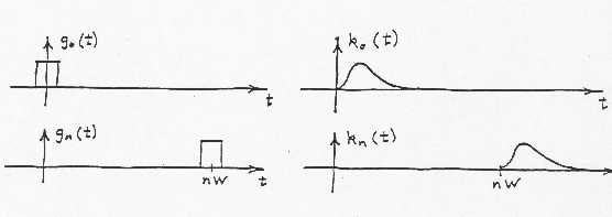
Let Description: Description: Description: C:\Users\gwang08\Desktop\MAE315\Website\MAE315\notesNrefs\Fourier\Image61.gif be a pulse of width W and height A:

Description: Description: Description: C:\Users\gwang08\Desktop\MAE315\Website\MAE315\notesNrefs\Fourier\Image62.gif

Let Description: Description: Description: C:\Users\gwang08\Desktop\MAE315\Website\MAE315\notesNrefs\Fourier\Image63.gif be a pulse of exactly the same shape, but delayed by (nW) seconds

Description: Description: Description: C:\Users\gwang08\Desktop\MAE315\Website\MAE315\notesNrefs\Fourier\Image64.gif

An approximation to an arbitrary x(t) can now be formed from a series of such pulses, with the height of each pulse adjusted to the value of x(t) at the point in time at which the pulse occurs:

Description: Description: Description: C:\Users\gwang08\Desktop\MAE315\Website\MAE315\notesNrefs\Fourier\Image65.gif


Description: Description: Description: C:\Users\gwang08\Desktop\MAE315\Website\MAE315\notesNrefs\Fourier\Image66.gif

(44)

Let the response of a given linear Stationary system to Description: Description: Description: C:\Users\gwang08\Desktop\MAE315\Website\MAE315\notesNrefs\Fourier\Image67.gif be Description: Description: Description: C:\Users\gwang08\Desktop\MAE315\Website\MAE315\notesNrefs\Fourier\Image68.gif:
 

Description: Description: Description: C:\Users\gwang08\Desktop\MAE315\Website\MAE315\notesNrefs\Fourier\Image69.gif

(45)

Since the system is stationary, the output Description: Description: Description: C:\Users\gwang08\Desktop\MAE315\Website\MAE315\notesNrefs\Fourier\Image70.gif, corresponding to the delayed input Description: Description: Description: C:\Users\gwang08\Desktop\MAE315\Website\MAE315\notesNrefs\Fourier\Image71.gif is simply Description: Description: Description: C:\Users\gwang08\Desktop\MAE315\Website\MAE315\notesNrefs\Fourier\Image72.gif delayed by (nW) seconds:
 

Description: Description: Description: C:\Users\gwang08\Desktop\MAE315\Website\MAE315\notesNrefs\Fourier\Image73.gif

(46)

Description: Description: Description: C:\Users\gwang08\Desktop\MAE315\Website\MAE315\notesNrefs\Fourier\Image74.gif

Because the system is linear, it obeys the principles of superposition. Thus we can use (43), (44), and (46) to approximate the output of the system, y(t), to an arbitrary input x(t):
 

Description: Description: Description: C:\Users\gwang08\Desktop\MAE315\Website\MAE315\notesNrefs\Fourier\Image75.gif

(47)

 Let us now define a quasi-continuous variable t as follows:


Description: Description: Description: C:\Users\gwang08\Desktop\MAE315\Website\MAE315\notesNrefs\Fourier\Image76.gif

(48)

Description: Description: Description: C:\Users\gwang08\Desktop\MAE315\Website\MAE315\notesNrefs\Fourier\Image77.gif

(49)

And, if we require that:
 

Description: Description: Description: C:\Users\gwang08\Desktop\MAE315\Website\MAE315\notesNrefs\Fourier\Image78.gif

(50)

Then in the limit as Description: Description: Description: C:\Users\gwang08\Desktop\MAE315\Website\MAE315\notesNrefs\Fourier\Image79.gif, we obtain from (42) and (45):
 

Description: Description: Description: C:\Users\gwang08\Desktop\MAE315\Website\MAE315\notesNrefs\Fourier\Image80.gif

(51)

Description: Description: Description: C:\Users\gwang08\Desktop\MAE315\Website\MAE315\notesNrefs\Fourier\Image81.gif

(52)

And, from (47) we obtain the Convolution Integral
 

Description: Description: Description: C:\Users\gwang08\Desktop\MAE315\Website\MAE315\notesNrefs\Fourier\Image82.gif

 (53)

Note: The upper limit of the integration for (53) could be changed from +¥to t without changing the value of the integral because Description: Description: Description: C:\Users\gwang08\Desktop\MAE315\Website\MAE315\notesNrefs\Fourier\Image83.gif for Description: Description: Description: C:\Users\gwang08\Desktop\MAE315\Website\MAE315\notesNrefs\Fourier\Image84.gif (principle of causality). Moreover, all practical inputs start at some finite time, and thus it is common to arrange the time axis so that Description: Description: Description: C:\Users\gwang08\Desktop\MAE315\Website\MAE315\notesNrefs\Fourier\Image85.gif for Description: Description: Description: C:\Users\gwang08\Desktop\MAE315\Website\MAE315\notesNrefs\Fourier\Image86.gif. Under these special conditions, (53) becomes:
 

Description: Description: Description: C:\Users\gwang08\Desktop\MAE315\Website\MAE315\notesNrefs\Fourier\Image87.gif

(53a)

This formula lends itself to computer calculations of the system response to an arbitrary input, once the impulse response h(t) has been recorded.

C: System Transfer Function

We can now calculate the Fourier transform of y(t), using (53) and our basic formula (26):
 

Description: Description: Description: C:\Users\gwang08\Desktop\MAE315\Website\MAE315\notesNrefs\Fourier\Image88.gif

(54)

Reversing the order of integration (i.e., interchanging the differentials), moving Description: Description: Description: C:\Users\gwang08\Desktop\MAE315\Website\MAE315\notesNrefs\Fourier\Image89.gif inside the first integral, moving Description: Description: Description: C:\Users\gwang08\Desktop\MAE315\Website\MAE315\notesNrefs\Fourier\Image90.gif outside the first integral, defining a new variable Description: Description: Description: C:\Users\gwang08\Desktop\MAE315\Website\MAE315\notesNrefs\Fourier\Image91.gif (which for purposes of the first integration, gives Description: Description: Description: C:\Users\gwang08\Desktop\MAE315\Website\MAE315\notesNrefs\Fourier\Image92.gif), and moving the resulting Description: Description: Description: C:\Users\gwang08\Desktop\MAE315\Website\MAE315\notesNrefs\Fourier\Image93.gif outside the first integral, yields:
 

Description: Description: Description: C:\Users\gwang08\Desktop\MAE315\Website\MAE315\notesNrefs\Fourier\Image94.gif


(55)

That is, the Fourier transform of the output is simply the Fourier transform of the input multiplied by the Fourier transform of the impulse response.

We can rewrite (55) as:
 

Description: Description: Description: C:\Users\gwang08\Desktop\MAE315\Website\MAE315\notesNrefs\Fourier\Image95.gif

(56)

Thus, for a given linear stationary system, the ratio of the Fourier transform of the output to the Fourier transform of the input is a characteristic function of the system, and is independent of the specific input and output. Hence, this characteristic function is often called the system transfer function.

As indicated by (56), we can find the system transfer function directly by simply recording (or calculating) the impulse response h(t) of the system, and then using a computer to calculate the Fourier transform of h(t). Or, we can record the response of the system to some other non-period input, and then use a computer to calculate the ratio of the Fourier transform of the response to the Fourier transform of the input.

D: Low-Pass Filter Example

Description: Description: Description: C:\Users\gwang08\Desktop\MAE315\Website\MAE315\notesNrefs\Fourier\Image96.gif

Let Description: Description: Description: C:\Users\gwang08\Desktop\MAE315\Website\MAE315\notesNrefs\Fourier\Image97.gif be a unit impulse Description: Description: Description: C:\Users\gwang08\Desktop\MAE315\Website\MAE315\notesNrefs\Fourier\Image98.gif. For practical purposes, let Description: Description: Description: C:\Users\gwang08\Desktop\MAE315\Website\MAE315\notesNrefs\Fourier\Image97.gifbe a pulse that is A volts high and (1/A) seconds wide, where A is very large. Under these conditions:
 

Description: Description: Description: C:\Users\gwang08\Desktop\MAE315\Website\MAE315\notesNrefs\Fourier\Image99.gif  for Description: Description: Description: C:\Users\gwang08\Desktop\MAE315\Website\MAE315\notesNrefs\Fourier\Image100.gif

(57)

Description: Description: Description: C:\Users\gwang08\Desktop\MAE315\Website\MAE315\notesNrefs\Fourier\Image101.giffor Description: Description: Description: C:\Users\gwang08\Desktop\MAE315\Website\MAE315\notesNrefs\Fourier\Image102.gif

(58)

The charge q residing on the capacitor after the pulse has passed through can be calculated:
 

Description: Description: Description: C:\Users\gwang08\Desktop\MAE315\Website\MAE315\notesNrefs\Fourier\Image103.gif

(59)

and hence the voltage on the capacitor just after the pulse has passed through is:
 

Description: Description: Description: C:\Users\gwang08\Desktop\MAE315\Website\MAE315\notesNrefs\Fourier\Image104.gif

(60)

Thus, the effects of the unit impulse at the input is to instantly charge the capacitor to (1/RC) volts. After the pulse, the voltage source x(t) becomes a short circuit (i.e., Description: Description: Description: C:\Users\gwang08\Desktop\MAE315\Website\MAE315\notesNrefs\Fourier\Image105.gif) and the capacitor discharges exponentially (with a time constant of RC) back through the resistor. Hence the impulse response of this system is:
 

Description: Description: Description: C:\Users\gwang08\Desktop\MAE315\Website\MAE315\notesNrefs\Fourier\Image106.gif

(61)

Description: Description: Description: C:\Users\gwang08\Desktop\MAE315\Website\MAE315\notesNrefs\Fourier\Image107.gif

Description: Description: Description: C:\Users\gwang08\Desktop\MAE315\Website\MAE315\notesNrefs\Fourier\Image108.gif

The system transfer function H(f) can now be found by computing the Fourier transform of h(t) using (26);
 

Description: Description: Description: C:\Users\gwang08\Desktop\MAE315\Website\MAE315\notesNrefs\Fourier\Image109.gif

(62)

Description: Description: Description: C:\Users\gwang08\Desktop\MAE315\Website\MAE315\notesNrefs\Fourier\Image110.gif

(63)

Description: Description: Description: C:\Users\gwang08\Desktop\MAE315\Website\MAE315\notesNrefs\Fourier\Image111.gif

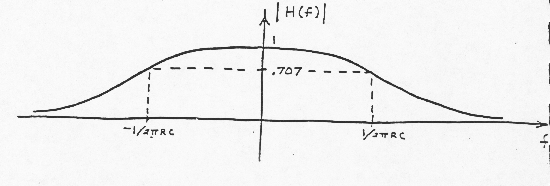
This filter passes the low frequencies, and attenuates or "filters out" the high frequencies.

E: Calculations of the System Transfer Function from the System differential Equation

If the system can be described by a linear stationary differential equation, the system transfer function can be easily obtained with the help of (31a).

For example, suppose the system is described by the following differential equation:
 

Description: Description: Description: C:\Users\gwang08\Desktop\MAE315\Website\MAE315\notesNrefs\Fourier\Image112.gif

(64)

Taking the Fourier transform of each term in the equation [with the help of (31a) yields:
 

Description: Description: Description: C:\Users\gwang08\Desktop\MAE315\Website\MAE315\notesNrefs\Fourier\Image113.gif

(65)

and hence:
 

Description: Description: Description: C:\Users\gwang08\Desktop\MAE315\Website\MAE315\notesNrefs\Fourier\Image114.gif

(66)

F: Low-Pass Filter Example (again)

Description: Description: Description: C:\Users\gwang08\Desktop\MAE315\Website\MAE315\notesNrefs\Fourier\Image115.gif

Charge q on capacitor C given by:
 

Description: Description: Description: C:\Users\gwang08\Desktop\MAE315\Website\MAE315\notesNrefs\Fourier\Image116.gif

(67)

Therefore, the current is:
 

Description: Description: Description: C:\Users\gwang08\Desktop\MAE315\Website\MAE315\notesNrefs\Fourier\Image117.gif

(68)

And, by Kirchoff’s voltage law, we have
 

Description: Description: Description: C:\Users\gwang08\Desktop\MAE315\Website\MAE315\notesNrefs\Fourier\Image118.gif

(69)

Taking the Fourier transform of each term in (69) yields:
 

Description: Description: Description: C:\Users\gwang08\Desktop\MAE315\Website\MAE315\notesNrefs\Fourier\Image119.gif

(70)

Since (70) is simply an algebraic equation, we can readily solve it for the system transfer function:
 

Description: Description: Description: C:\Users\gwang08\Desktop\MAE315\Website\MAE315\notesNrefs\Fourier\Image120.gif

(71)

This is, of course, exactly the same result that we obtained before [see (62)] by calculating the Fourier transform of the impulse response.

Description: Description: Description: C:\Users\gwang08\Desktop\MAE315\Website\MAE315\notesNrefs\Fourier\Image121.gif

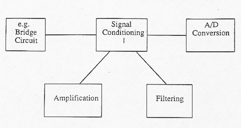
In many cases signals from transducers are weak and hence must be amplified before they can be digitized or used to drive some output device.

In other instances there is an impedance mismatch between that of the transducer and that of the output circuits hence an interface must be provided to allow effective impedance matching.

The ratio of output to input for an electronic signal condition device is referred to as:

- Gain or amplification ratio (if > 1)

- Attenuation if < 1.

It may be defined as voltages, currents, or powers.

Voltage gain = voltage output/voltage input

Current gain = current output/current input

Power gain = power output/power input

Decibel (dB) = 10 log10(P2/P1)

e.g.

Average human ear can detect a loudness change from an audio amplifier when a power ratio change of 1 dB is made. This is generally true of the power level.

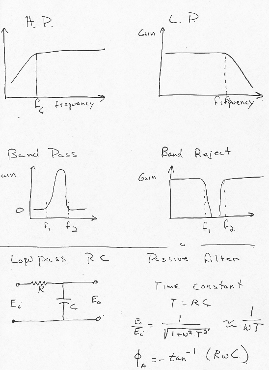
Filters

  • Time signals consist of many frequency components or harmonics
  • Many times noise is picked up which masks the true signal
  • Often possible to filter out unwanted noise
  • Also use low pass filter for antialiasing purposes.

Filtering is the process of attenuating unwanted frequencies in an input signal while permitting the desired components to pass.

Two classes of filters

Active – uses powered components general configuration of op amps.

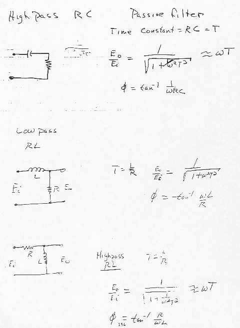
Passive – made up of R-C-L type circuits

Four types of filters

high – pass

low – pass – anti aliasing

band – pass

band – reject or notch filters

Description: Description: Description: C:\Users\gwang08\Desktop\MAE315\Website\MAE315\notesNrefs\Fourier\Image122.gif

Description: Description: Description: C:\Users\gwang08\Desktop\MAE315\Website\MAE315\notesNrefs\Fourier\Image123.gif

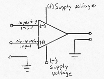
Operational Amplifiers

d.c. differential voltage amplifier

By d.c. we mean that it will process inputs over a frequency range down to and including d.c. voltage.

Description: Description: Description: C:\Users\gwang08\Desktop\MAE315\Website\MAE315\notesNrefs\Fourier\Image124.gif

Output from non-inverting input (+) is in phase with the input.

Output from inverting input (-) is 180° out of phase.

Characteristics of OP amps

  1. high input impedance (mega ohms to giga ohms)
  2. low output impedance (as low as a fraction of an ohm)
  3. Capable of very high gain [106 (120dB) or >]
  4. The are quite effective in rejecting common mode inputs

Typical OP amp specifications

OP amp 741 best known

Open loop gain to 105 (frequency dependent)

Maximum power supply voltage ± 18V

Power Dissipation 500mW

Maximum differential input voltage ± 30V

Maximum single-ended ± 15V

The output is a function of the difference between the two input signals, hence called the differential amplifiers.

  • If the inputs to the (+) and (-) ports are identical, ideally the net output of the op amp will be zero.
  • this leads to a very useful property called common mode rejection (CMR).
  • Generally a useful signal may be applied to one of the inputs while the other is tied to ground.
  • The signal would then be equal to the input multiplied by the gain.
  • However, external elements, leads, etc. may pick up unwanted noise such as stray 60-cycle line hash.
  • Fortunately such noise is generally more or less equally applied to both inputs on outputs and therefore is largely cancelled by the CMR characteristic of the amplifier.

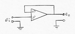
Example 1 – Impedance transformer or voltage follower

Description: Description: Description: C:\Users\gwang08\Desktop\MAE315\Website\MAE315\notesNrefs\Fourier\Image125.gif

  1. full output fed to (-) input by feedback loop
  2. Gain = 1, Phase of e0 lags eI by 180° .
  3. Input impedance in giga ohms, output impedance in fractions of an ohm.

Description: Description: Description: C:\Users\gwang08\Desktop\MAE315\Website\MAE315\notesNrefs\Fourier\Image126.gif

  1. Most used of all op-amp circuits
  • Feedback provided by R2
  • Differential input across (-) and (+) provided an output equal to the voltage difference multiplied by circuit gain. Output is out of phase with input.
  1. Circuit gain = R2/R1
  2. R3 = (R1R2)/(R1+R2) provides nearly equal input at (+) and (-) terminals.

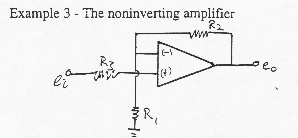
Description: Description: Description: C:\Users\gwang08\Desktop\MAE315\Website\MAE315\notesNrefs\Fourier\Image127.gif

  1. Output in phase with input e0 = eI times the gain.
  2. Gain = (R1+R2)/R1
  3. R3 serves the same purpose as for example 2.

Other examples:

  • voltage comparator
  • summing amplifier
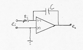
  • the integrator

e.g. the integrator

Description: Description: Description: C:\Users\gwang08\Desktop\MAE315\Website\MAE315\notesNrefs\Fourier\Image128.gif

Description: Description: Description: C:\Users\gwang08\Desktop\MAE315\Website\MAE315\notesNrefs\Fourier\Image129.gif

Active Filters - Analysis of active versions of the low pass filter

Description: Description: Description: C:\Users\gwang08\Desktop\MAE315\Website\MAE315\notesNrefs\Fourier\Image130.gif

We want a relationship between output voltage and input voltage vi. Assume all voltage and circuits are simple single-frequency sinusoids
 

Description: Description: Description: C:\Users\gwang08\Desktop\MAE315\Website\MAE315\notesNrefs\Fourier\Image131.gif

Description: Description: Description: C:\Users\gwang08\Desktop\MAE315\Website\MAE315\notesNrefs\Fourier\Image132.gif

Description: Description: Description: C:\Users\gwang08\Desktop\MAE315\Website\MAE315\notesNrefs\Fourier\Image133.gif

Description: Description: Description: C:\Users\gwang08\Desktop\MAE315\Website\MAE315\notesNrefs\Fourier\Image134.gif

We use the above reference directions to write

                                 i1 = (νi – ν1) /  R                                                                    (1)

                                 i2 = ν2 /R

                                 i3 = -C(dν1 / dt)

                                 i4 = (ν0 – ν2) / ((k -1)R)


Where the ground voltage is taken to be 0.

Remember

Input impedance is infinity at + terminals
 

Description: Description: Description: C:\Users\gwang08\Desktop\MAE315\Website\MAE315\notesNrefs\Fourier\Image139.gif

(2)

Description: Description: Description: C:\Users\gwang08\Desktop\MAE315\Website\MAE315\notesNrefs\Fourier\Image140.gif

Using 1 with the sinusoids substituting equation 2 becomes:
 

Description: Description: Description: C:\Users\gwang08\Desktop\MAE315\Website\MAE315\notesNrefs\Fourier\Image141.gif

Description: Description: Description: C:\Users\gwang08\Desktop\MAE315\Website\MAE315\notesNrefs\Fourier\Image142.gif

Take d/dt and cancel common factors, we arrive at:
 

Description: Description: Description: C:\Users\gwang08\Desktop\MAE315\Website\MAE315\notesNrefs\Fourier\Image143.gif

(3a)

Description: Description: Description: C:\Users\gwang08\Desktop\MAE315\Website\MAE315\notesNrefs\Fourier\Image144.gif

(3b)

Now:
 

                                ν0 = A(ν1- ν2)

Or by substituting the sinusoids:
 

Description: Description: Description: C:\Users\gwang08\Desktop\MAE315\Website\MAE315\notesNrefs\Fourier\Image146.gif

A @ infinity \ if v0 is to be finite V1 @ V2!

Solving for V1 in (3a) and V2 in (3b) and equating them gives:
 

Description: Description: Description: C:\Users\gwang08\Desktop\MAE315\Website\MAE315\notesNrefs\Fourier\Image147.gif

Description: Description: Description: C:\Users\gwang08\Desktop\MAE315\Website\MAE315\notesNrefs\Fourier\Image148.gif

This is complex.

In terms of the amplitude only
 

Description: Description: Description: C:\Users\gwang08\Desktop\MAE315\Website\MAE315\notesNrefs\Fourier\Image149.gif

Compare to passive RC filter. Note the k, which is an amplification factor.

\ Can use filter arranged as LP filter and amplifier!!