Introduction:
Universal Modeling Language (UML) diagrams are used to represent the structure and processing of software systems. Their purpose is to abstract away all the details in source code, leaving only the essential structure and relationships. Here are several different types of UML diagrams:-
Packages:
Show packages1 that make up a system and their calling relationships. -
Activites:
Describe the sequencing of major processing activities. -
Classes:
Show the classes in a subsystem and their relationships, e.g., inheritance, composition, aggregation, and using. The diagram may show class methods and data, but need not, if that isn't important for the discussion. -
States:
State diagrams are used to show the sequencing of designated activities, emphasizing their transitions from one state to another.
Example Package Diagram:
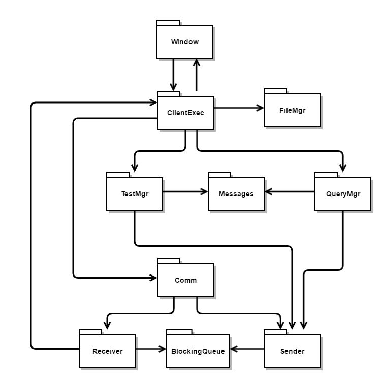
Client Package Diagram
Example Activity Diagram:
Activity diagrams describe the sequencing of blocks of processing, called activites, and are represented by the text blocks in this diagram.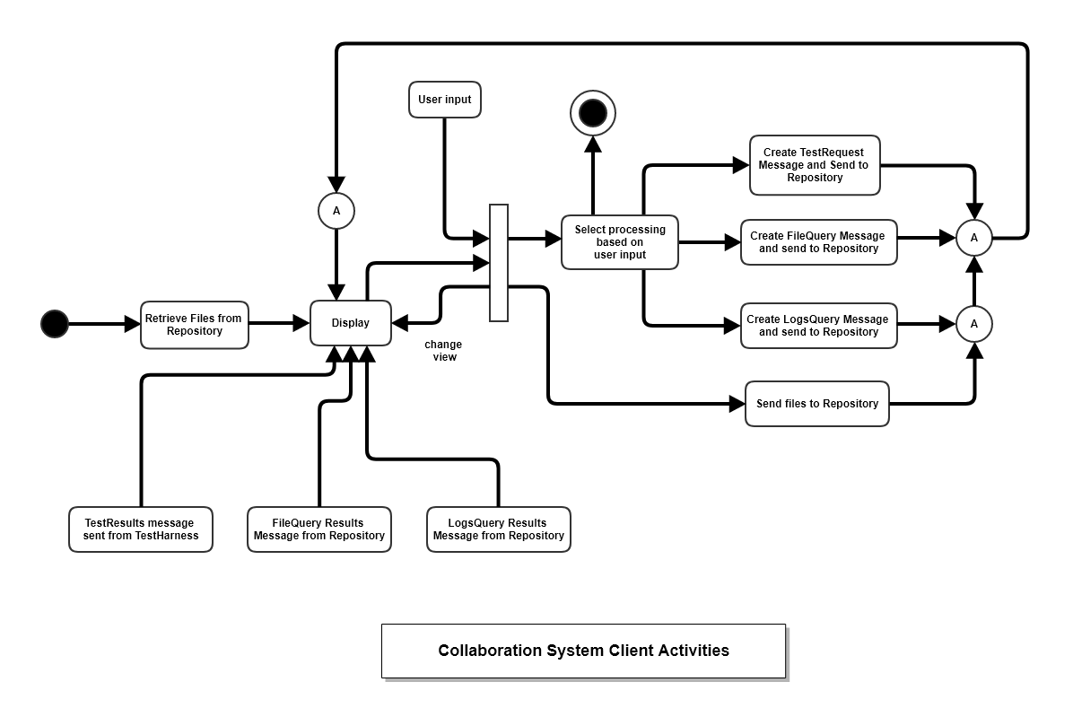
Client Activity Diagram
Example Class Diagram:
Class diagrams describe the logical structure of a program, describing the important classes and their relationships. There are four such relationships:-
Inheritance:
Symbolically represented by a directed path with triangle incident on the base class connecting with one or more derived classes. -
Composition:
A strong ownership relation between an owner class and owned value type, represented by a directed path with solid fill diamond incident on the composing class, connecting with a composed type. Since, in managed languages like C#, only value types, all primitives and structs, can be composed, we rarely show them on class diagrams2. Composed types lie within the memory footprint of the composing class, and the composer does not call new to create an instance. That happens when the composing class is created. -
Aggregation:
A weaker ownership relation, between an aggregator and aggregated type, is represented by a directed path with non-filled diamond, incident on the aggregating class, connecting with the aggregated class. In this case, the aggregated instance occupies a region of the managed heap outside the bounds of the aggregating class. The aggregated instance does not exist until some code in the aggregator creates it with a call to new. -
Using:
Using relationships represent a non-owning relationship between the using class and the used class instance. The used resource is created by some other entity, not the using class, and is passed to the user via a function call.
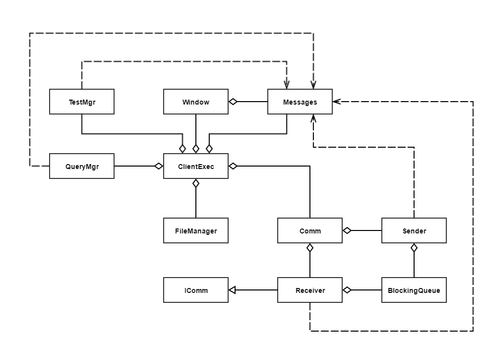
Client Class Diagram
- Remember that, in C#, a package is a single source code file, endowed with Prologue, Manual, and Maintenance comments, followed by class definitions, and finally a test stub enclosed by a compiler directive to include or not include compilation of its main function.
- In native languages, like C++, one class instance can compose an instance of another class and most designs use those relationships frequently.
- Note that many C# and Java developers use the term composition between instances of classes, but these relationships, as discussed above, are aggregations not compositions.